Deploy a Fortigate Virtual Firewall
Purpose of this guide
This guide details the essential steps to effectively deploy an individual firewall or a firewall cluster in a SecNumCloud environment.
Note: The configurations presented in this document serve as a reference guide and must be carefully adapted to the specific technical requirements, security requirements, and operational objectives of each environment
Prerequisites for this guide
Required rights
Deploying virtual appliances requires access to the client's tenant in the Cloud Temple console with the following specific permissions:
If you are using the OpenIaaS offer:
| Permission Name | Permission Description |
|---|---|
| compute_iaas_opensource_console_access | OpenIaaS Offer - Opening the console of a virtual machine |
| compute_iaas_opensource_infrastructure_read | OpenIaaS Offer - Viewing advanced data of VMware resources (affinity/anti-affinity rules, DRS configuration, etc) |
| compute_iaas_opensource_infrastructure_write | OpenIaaS Offer - Advanced management of VMware resources |
| compute_iaas_opensource_read | OpenIaaS Offer - Viewing resources of type Virtual Machines |
| compute_iaas_opensource_management | OpenIaaS Offer - Management of resources of type Virtual Machines |
| compute_iaas_opensource_virtual_machine_power | OpenIaaS Offer - Power management of a virtual machine |
| activity_read | Viewing log files and activities |
If you are using the Vmware offer:
| Permission Name | Permission Description |
|---|---|
| compute_iaas_vmware_console_access | Vmware Offer - Opening the console of a virtual machine |
| compute_iaas_vmware_infrastructure_read | Vmware Offer - Viewing advanced data of VMware resources (affinity/anti-affinity rules, DRS configuration, etc) |
| compute_iaas_vmware_infrastructure_write | Vmware Offer - Advanced management of VMware resources |
| compute_iaas_vmware_read | Vmware Offer - Viewing resources of type Virtual Machines |
| compute_iaas_vmware_management | Vmware Offer - Management of resources of type Virtual Machines |
| compute_iaas_vmware_virtual_machine_power | Vmware Offer - Power management of a virtual machine |
| activity_read | Viewing log files and activities |
If you want to use Terraform, the following additional permissions are required:
| Permission Name | Permission Description |
|---|---|
| tag_read | Viewing tags, except RTMS tags |
| tag_write | Managing tags, except RTMS tags |
| iam_read | Viewing user rights |
| iam_write | Managing user rights |
The OVA image of the appliance to deploy must be available before starting the process. You can find Fortinet images on the support site. You need to have a Fortinet support account.
Go to the Download section then Firmware Images:
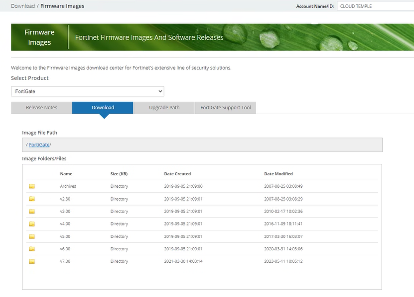
As of July 1st, 2024, version 7.2 is recommended.
The image to retrieve is FGT_VM64 in OVF/ZIP format:
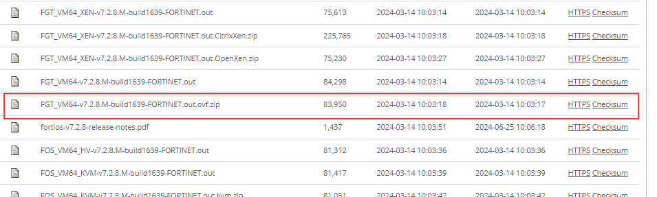
Note: If you have subscribed to a Fortinet firewall work unit, Cloud Temple support can provide the image in OVA format as well as the associated license.
| Infrastructure Work Units - VIRTUAL FIREWALLS | Unit | sku |
|---|---|---|
| FIREWALL UTM -Fortigate Virtuel VM02V - sans vdom | 1 virtual cluster | csp:fr1:licence:fw:ftg2 |
| FIREWALL UTM -Fortigate Virtuel VM04V - sans vdom | 1 virtual cluster | csp:fr1:licence:fw:ftg4 |
| FIREWALL UTM -Fortigate Virtuel VM08V - sans vdom | 1 virtual cluster | csp:fr1:licence:fw:ftg8 |
| FIREWALL UTM -Fortigate - 5 vdom complémentaires | 5 vdom | csp:fr1:licence:fw:vdom |
Network connectivity information
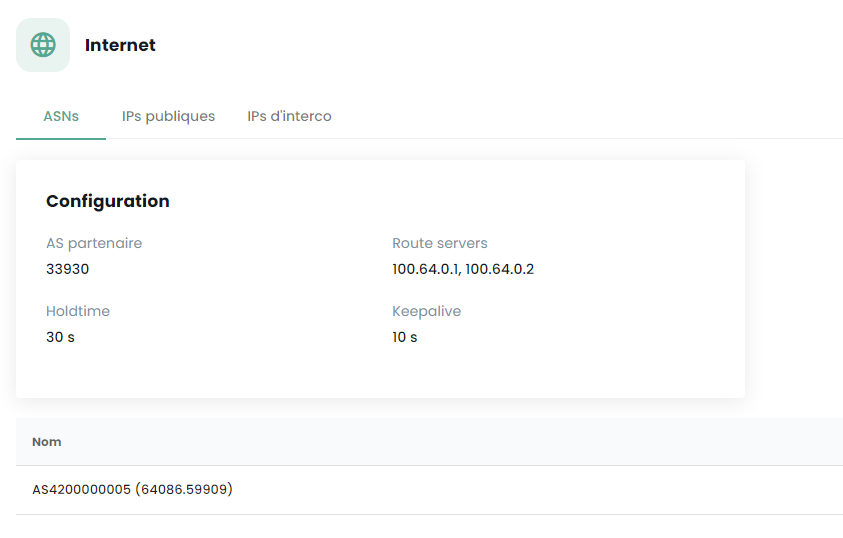
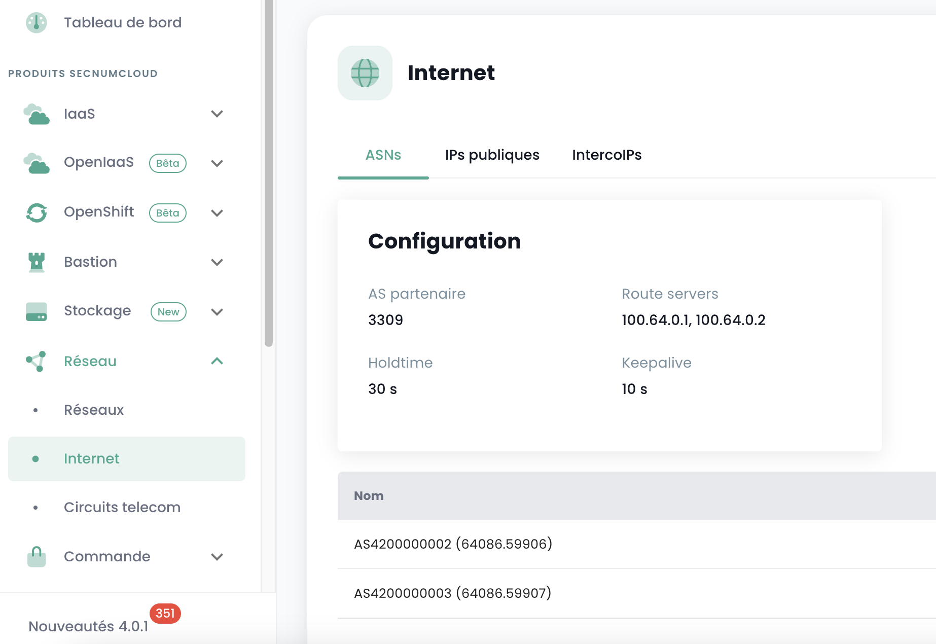
You must have the necessary information to establish the BGP session with the backbone. This data is available in the Cloud Temple console, in the Network → Internet → ASNs section:
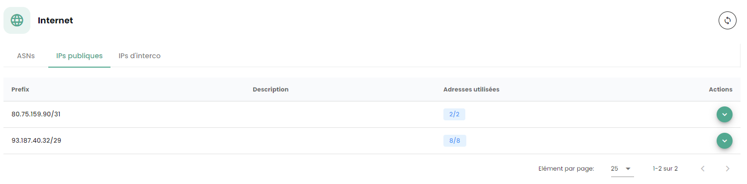
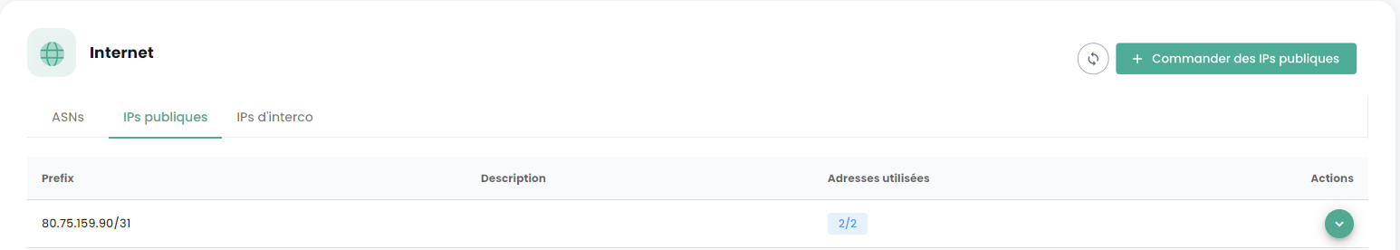
You must also have a public IP address range whose scope relates to your needs. The reserved address range is indicated in the Cloud Temple console under Network → Internet → Public IPs. Here is an example:
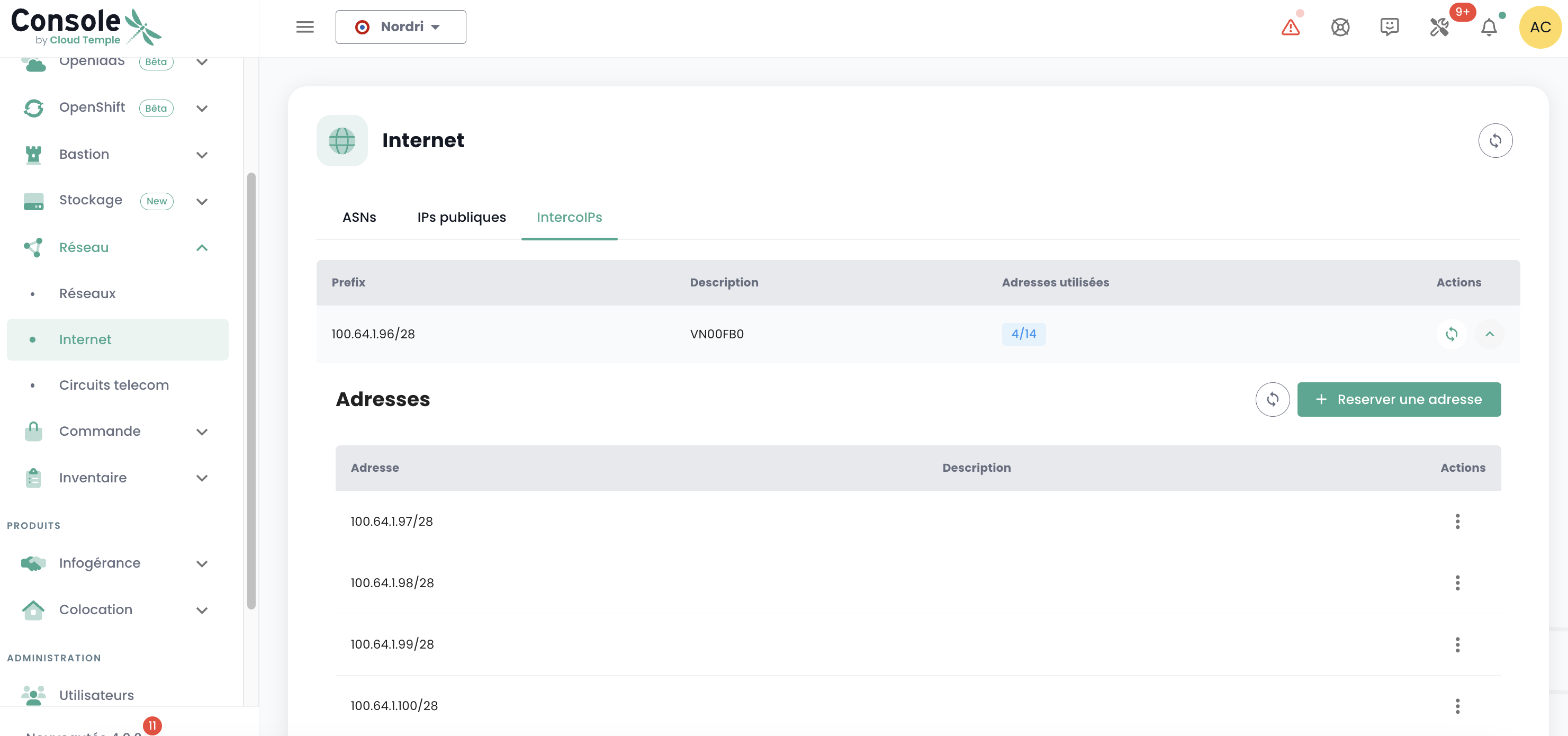
Finally, you must have the block allocated to you on the BGP interconnection network in order to benefit from a route to the Internet. The Cloud Temple interconnection network is 100.64.0.0/16 and each access benefits from a /28 interconnection subnet. This network is used to establish the BGP session with the Cloud Temple routing core. You will find this range in the Cloud Temple console in the Network → Internet → Interconnection IPs section. Here is an example:
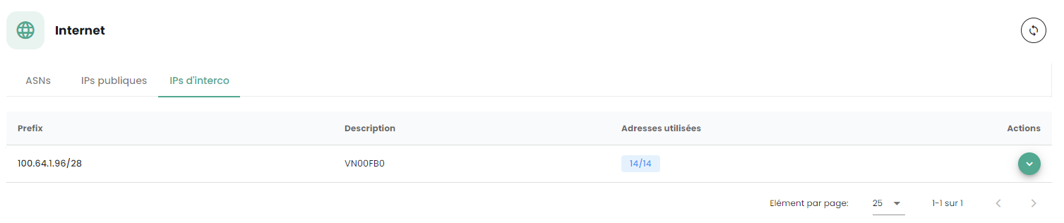
Note: You must have subscribed to the associated Internet connectivity units. You will then see the connectivity information appear in the Cloud Temple console.
Typical Network Architecture
The typical architecture for a Cloud Temple deployment is a High Availability Cluster. It involves implementing and subscribing to at least 2 availability zones within a region.
The standard firewall deployment is done in a cluster, with a device in each SNC availability zone. A virtual network ensures cluster synchronization. The WAN ports access the Internet via the interconnection network.
A initial configuration is required to establish BGP sessions, thus enabling Internet connectivity. Private VLANs are routed to the virtual firewall's LAN interfaces via a trunk (Layer 2 network aggregation using 802.1q technology).
Note: Although not a recommended architecture, this guide also applies to single-AZ deployments.
Importing the Fortinet Appliance into the Cloud Temple Console
Decompressing the Appliance File
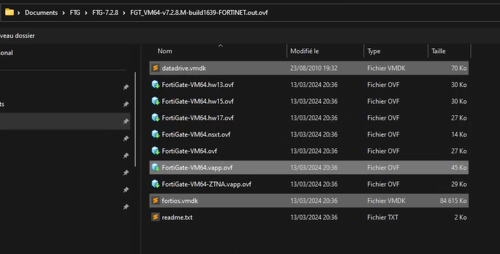
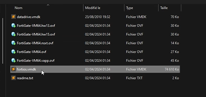
After downloading from the Fortinet support site, decompress the ZIP file to obtain:
-
The virtual VMDK disks of the appliance,
-
The OVF files describing the appliance for different VMware virtual hardware formats.
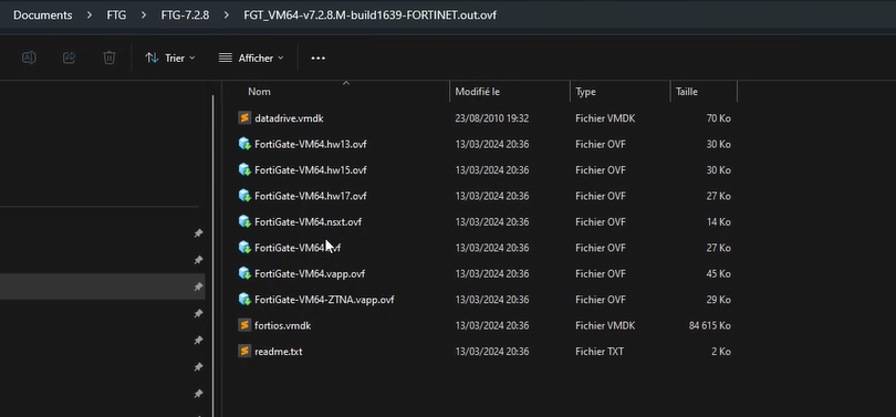
Here are the types of templates commonly included in the .ZIP:
| Template | Compatible with |
|---|---|
| FortiGate-VM64.ovf | ESXI 8.0 (Hardware Version 20) or later |
| FortiGate-VM64.hw13.ovf | ESXI 6.5 (Hardware Version 13) or later |
| FortiGate-VM64.hw15.ovf | ESXI 6.7U2+ (Hardware Version 15) or later |
| FortiGate-VM64.hw17.ovf | ESXI 7.0 (Hardware Version 17) or later |
| FortiGate-VM64.vapp.ovf | ESXI 8.0 (Hardware Version 20) or later |
| FortiGate-VM64.nsxt.ovf | ESXI 6.7U2+ (Hardware Version 15) or later |
| FortiGate-VM64-ZNTA.vapp.ovf | ESXI 7.0 (Hardware Version 17) or later |
Importing the Appliance into Your Image Catalog via the Cloud Temple Console
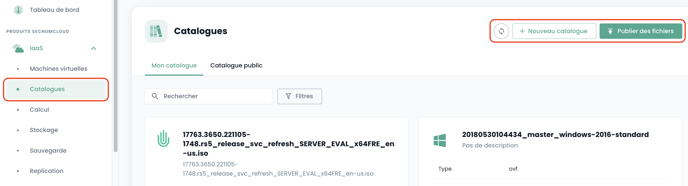
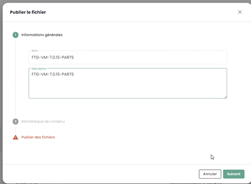
Log in to your tenant within the Cloud Temple console, then go to "Catalog" and "Publish Files":
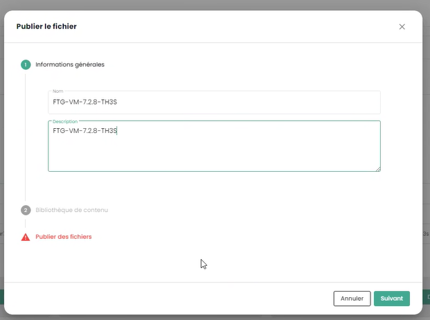
Choose a name for your image. We recommend using: FGT-VM-VERSION-AZ, for example here FGT-VM-7.2.8-TH3S:
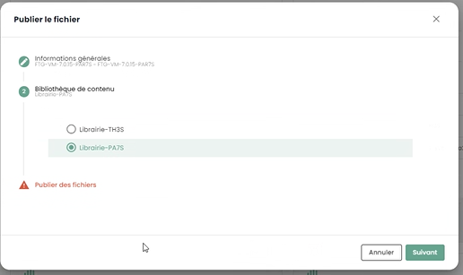
Indicate the image library of the availability zone (1):
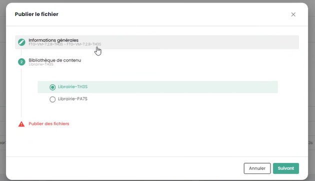
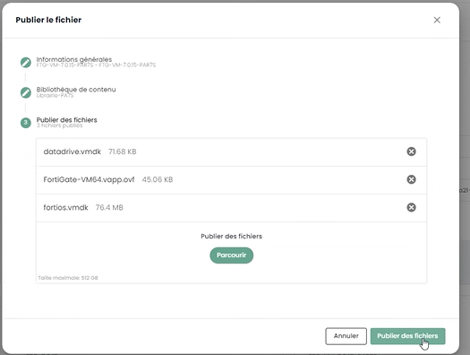
Then select the files to publish in the library (2):
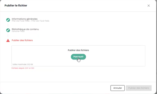
Click on "Publish Files":
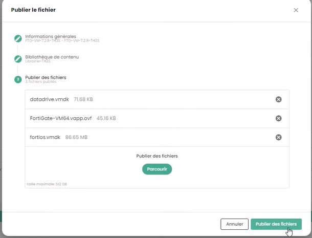
Wait for the end of the file download in the library:


The operation must be repeated for each availability zone where you want to deploy an appliance.
For example, for the second zone PAR7S:

Note:
-
(1) Each availability zone has an image library for the hypervisors of that zone.
-
(2) For the .ovf file, choose a version whose virtual hardware is compatible with the ESXi hypervisor version (as of July 1st, 2024, the maximum supported version is v19 corresponding to ESX 7.0.x).
Deploying the Fortinet Appliance on an Availability Zone
Planning Your BGP Interconnection Deployment
You must select an interconnection IP address for your future Firewall appliance. The first address is always the Cloud Temple BGP gateway. The other addresses are therefore generally available (unless you have previously deployed other equipment):
The rule is to take the free IPs in sequence:

Planning the Use of Your Public IP Addresses
All allocated public IP addresses are usable for your tenant. The size of the subnet depends on the units subscribed.
BGP4 Configuration Parameters
Note the following three important pieces of information for the BGP4 configuration:
-
Partner AS: the remote AS used to establish the BGP session from the firewall's perspective, it is the Cloud Temple AS.
-
Route Servers: the two BGP peers to which to establish a BGP session.
-
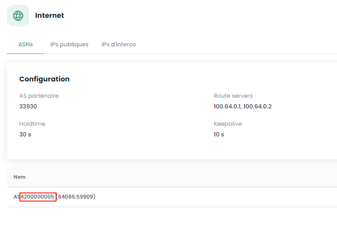
Name: the AS number specific to the tenant; remove the AS prefix to keep only the number.
Deploying the Appliance on the Infrastructure
From the availability zone's library where you want to install your appliance, select the template and then "Deploy":
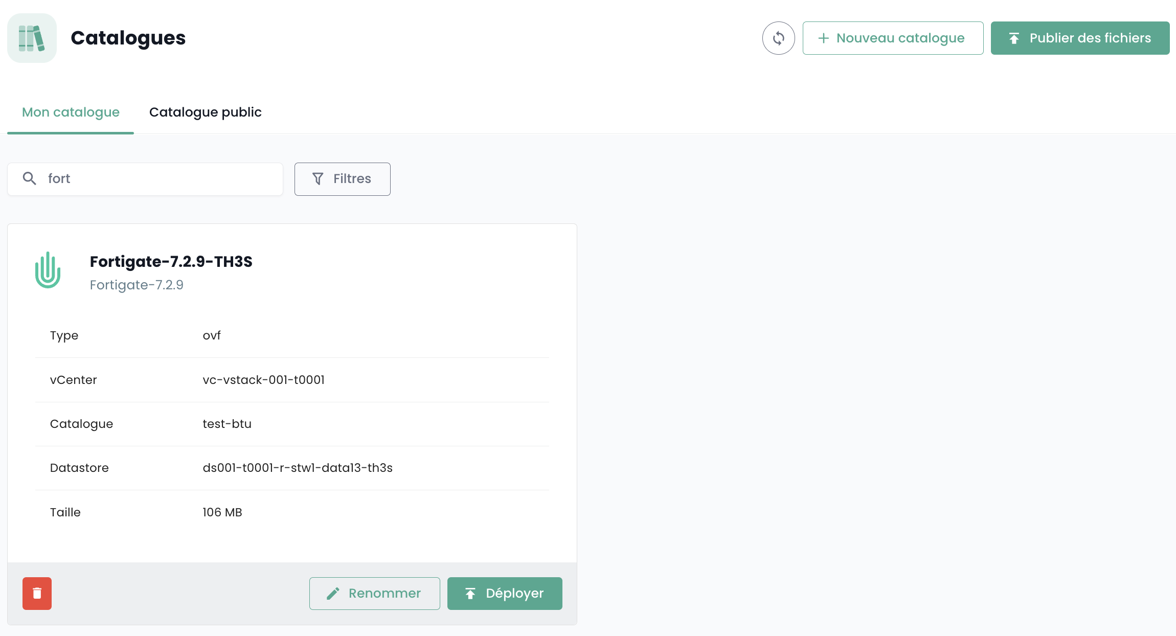
You must then name the virtual machine; we recommend the following naming convention: FGT-VM-0X-ROLE-AZ
- 0X: corresponds to the type of Fortigate license you have subscribed to:
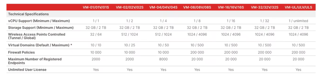
-
ROLE: For example INTERNET for an Internet connectivity firewall.
-
AZ: The availability zone
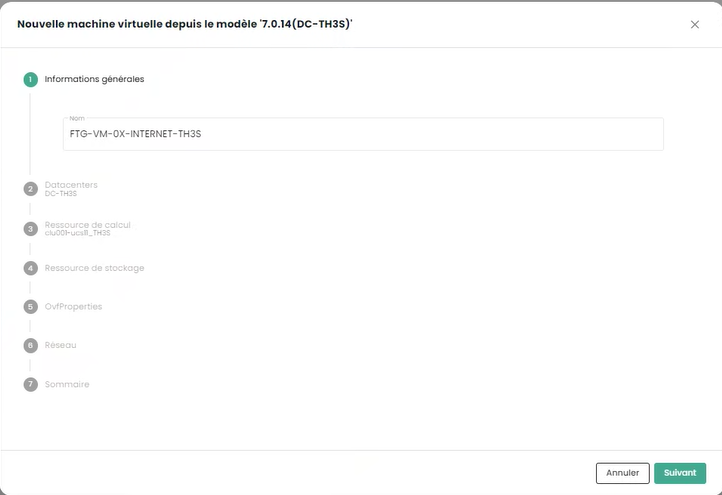
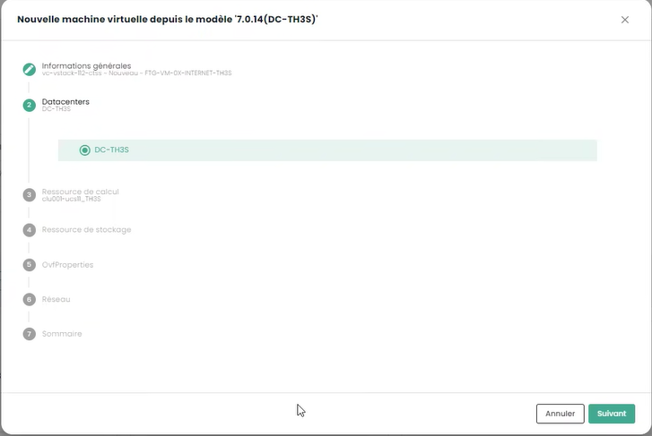
Select the availability zone next:
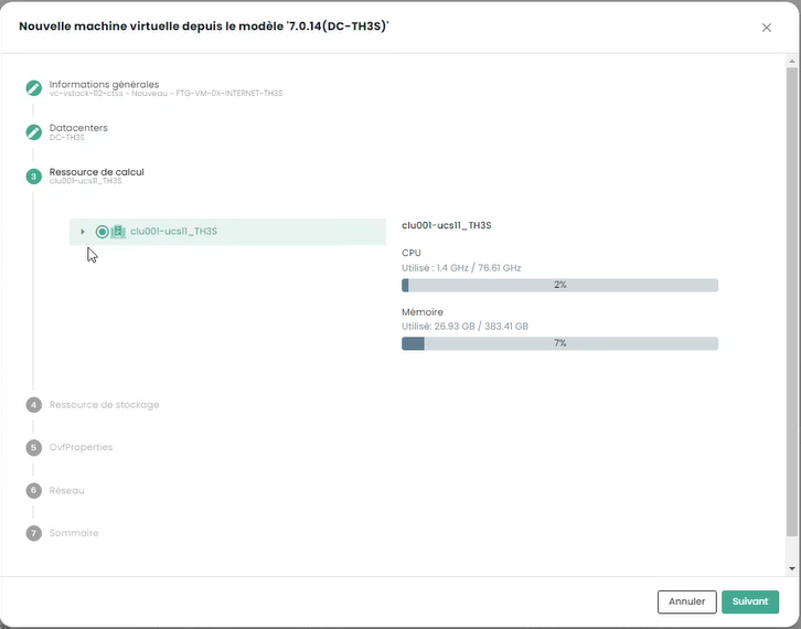
Then the target hypervisor cluster:
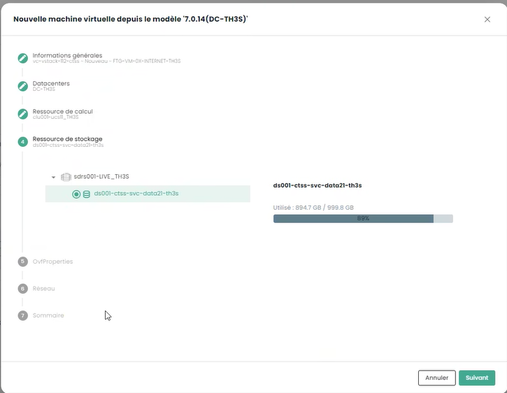
Choose the storage target:
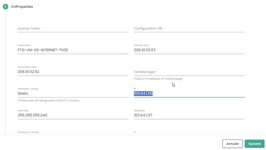
Finally, enter your appliance's configuration information, including the addressing information obtained previously:
-
Token: leave blank
-
Configuration URL: leave blank
-
Hostname: same as the VM's name
-
DNS: 208.91.112.53 and 208.91.112.2 (default, but you can choose other DNS as needed)
-
Interface IP: first free interconnection IP
-
Netmask: netmask of the interconnection range
-
Interface 2: not configured
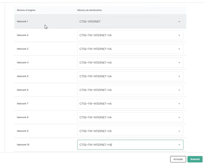
Click then on Next. Enter the interface configuration information. The first interface is used for Internet access; the others are temporarily set to the high availability VLAN:
Finally, click on "Deploy".
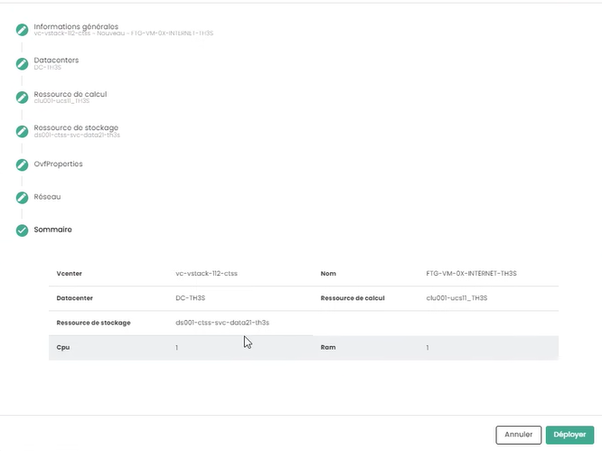
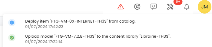
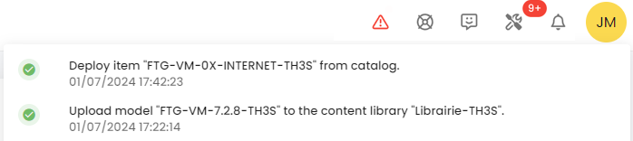
When the deployment is complete, the Cloud Temple console indicates it:
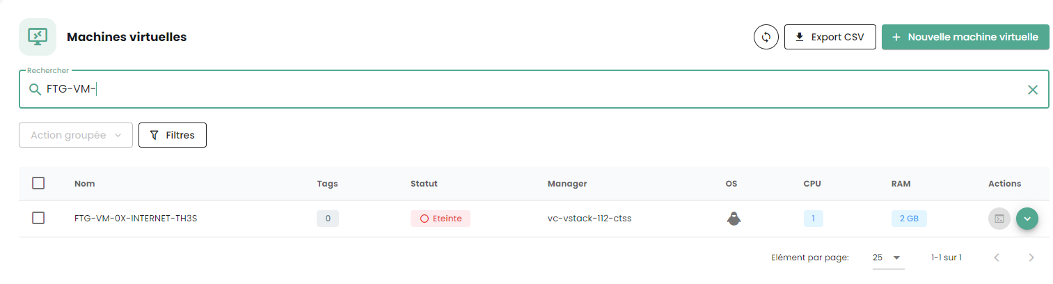
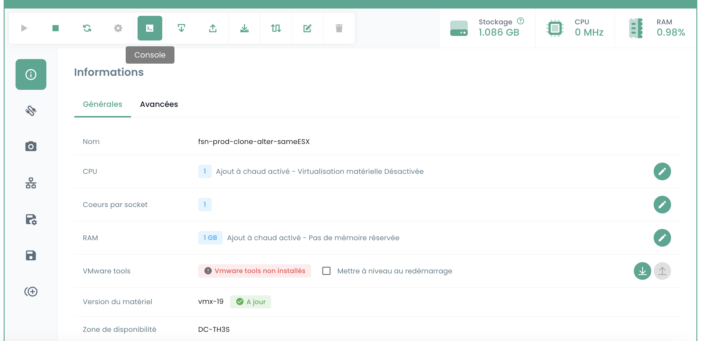
Your appliance is now visible in the virtual machines:
Assigning a Backup Policy
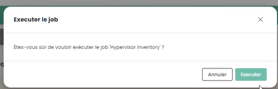
In the SecNumCloud environment, a virtual machine must have a backup policy to start. You can configure it in the policies and launch the inventory task:
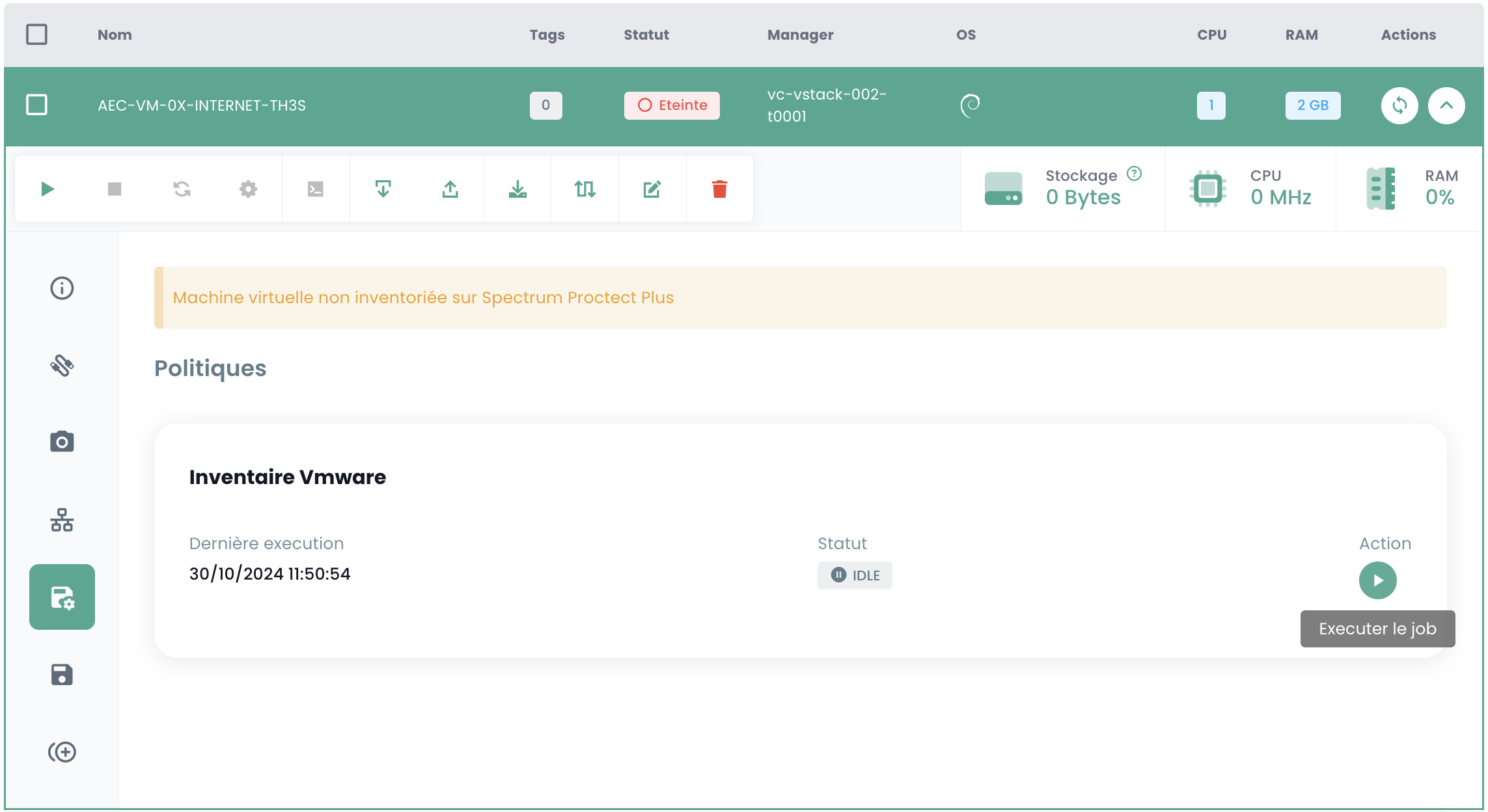
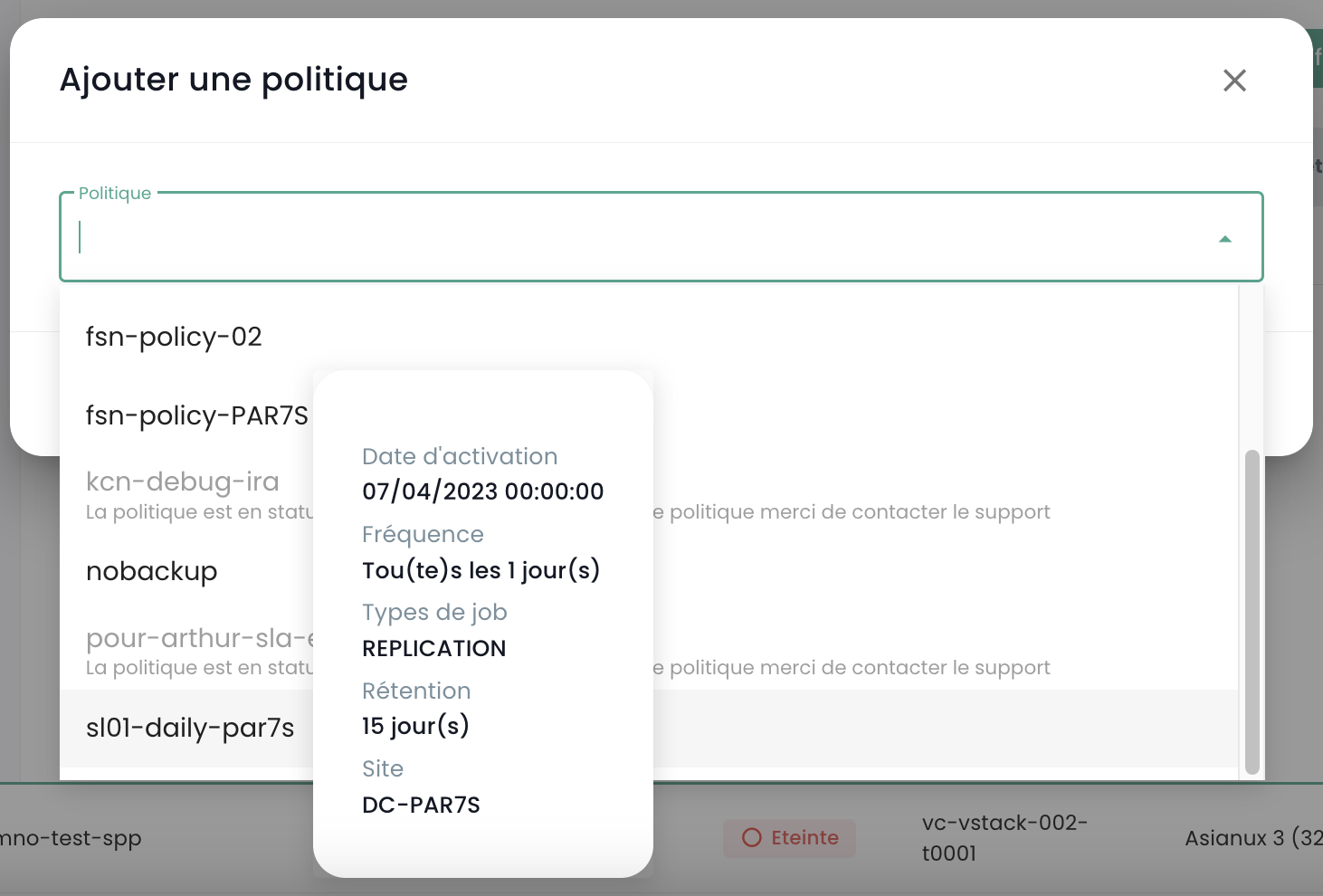
Assign the policy corresponding to the desired RPO, by default you can choose a daily policy:
You can confirm your choice:
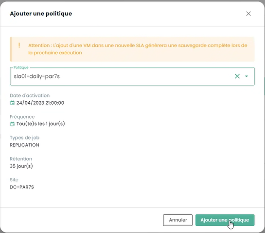
If additional policies are required (as in this example 'daily' and 'monthly'), repeat the operation for each additional policy.
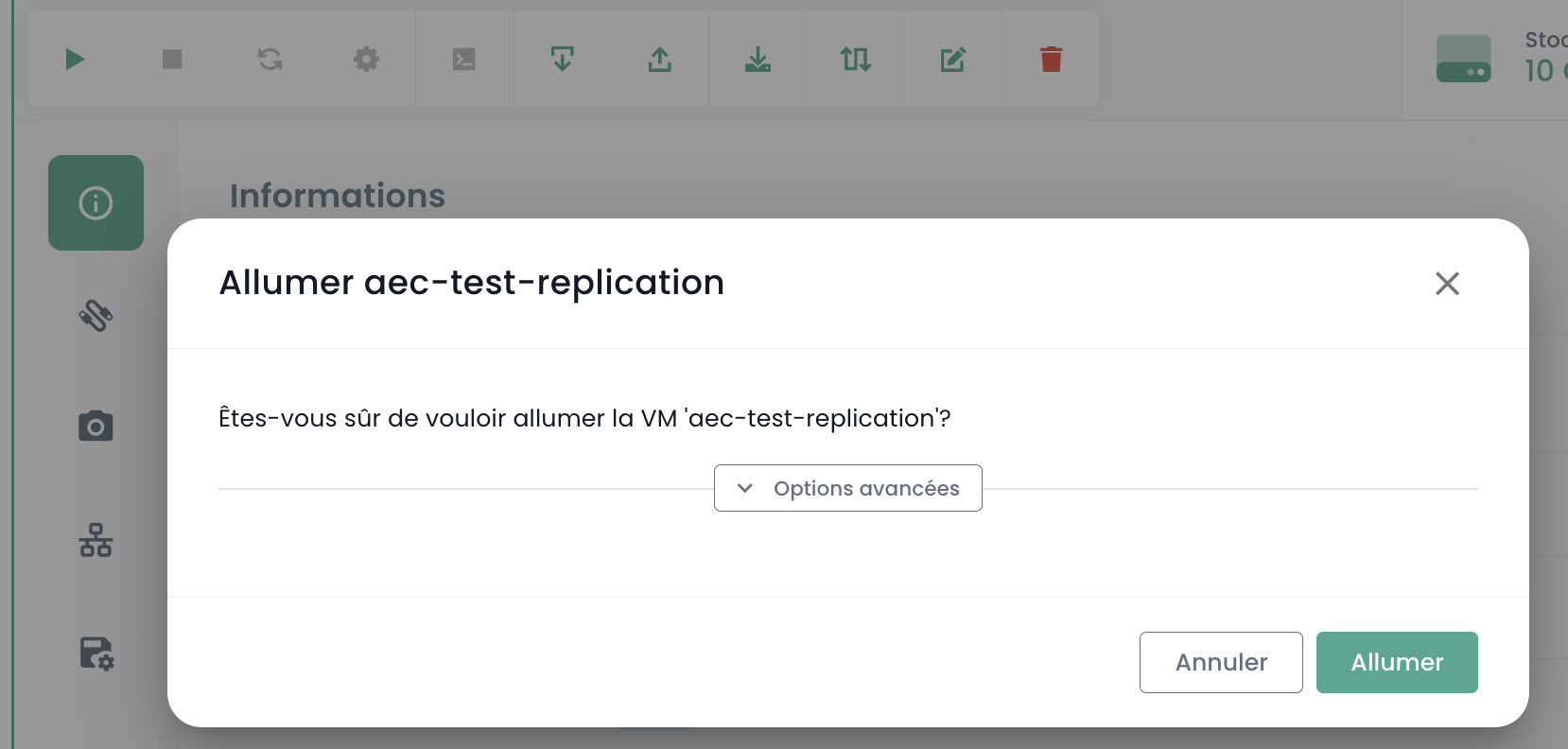
Starting the Virtual Machine
Starting the virtual machine is done from the Cloud Temple console:
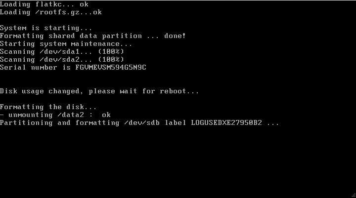
You can observe the console and the Fortinet appliance rebooting after the first boot:

After this second boot, the IP address indicated in the virtual machine deployment section OvfProperties should respond to a ping, provided there is access to the interconnection network.
Initial Configuration
Connecting to the Console
In the Cloud Temple console, select your Fortinet appliance and request the appliance's console.
Depending on when you access the console, you may have seen the initial boot and reboot of the appliance:

You can then connect to the appliance's console, the username is "admin". The appliance will ask you to change the password (there is no default password, just press ENTER).
You must then enter a new password.
Warning: The appliance uses a QWERTY keyboard.
In case of password error, you will have to reinstall your appliance.


Configuring the BGP Session
In this step, we will configure your Fortinet appliance in console mode to establish the BGP4 link.
Configuring the Public IP Range
The first step is to define the public IP address ranges. To start, we will configure only the first block. We will use the information you previously noted.
config router prefix-list edit "pfx_net_public_customer" config rule edit 1 set prefix 80.75.159.90/31 unset ge set le 32 next edit 100 set action deny set prefix 0.0.0.0 0.0.0.0 unset ge unset le next end next edit "pfx_deny_all" config rule edit 1 set action deny set prefix 0.0.0.0 0.0.0.0 unset ge unset le next end next end
You can then verify that the configuration has been successfully applied with the command:
show router prefix-list
Configuration of the route map
A "route map policy" is used to define more complex routing policies that can influence or modify the behavior of network traffic based on specific criteria. Route maps are particularly useful for advanced traffic management tasks, such as route filtering, traffic redirection, or modifying route attributes in dynamic routing protocols like BGP (Border Gateway Protocol). In our context, it aims to secure your network from invalid announcements.
The second step is to configure the route map policy:
config router route-map edit "rm_deny_all" config rule edit 1 set match-ip-address "pfx_deny_all" next end next edit "rm_net_public_customer" config rule edit 1 set match-ip-address "pfx_net_public_customer" next end next end
You can then verify that the configuration has been successfully applied with the command:
show router route-map
Configuration of the BGP announcement
We will now configure the BGP announcement. You must have, as seen earlier in this guide, the interconnection IP (here, the router-id), the BGP4 peer IP address (here, 100.64.0.1 and 100.64.0.2), the local AS (here 4200000005) and the previously configured public IP range. Remember:
and
In this configuration, the AS (autonomous system) of Cloud Temple is 33930. The AS 65001 is a private AS that represents you. Using a private AS number at this level is more appropriate, especially if multiple BGP connections need to be configured.
config router bgp set as 65001 set router-id 100.64.1.110 set network-import-check disable set graceful-restart enable config neighbor edit "100.64.0.1" set capability-graceful-restart enable set ebgp-enforce-multihop enable set next-hop-self enable set soft-reconfiguration enable set ebgp-multihop-ttl 3 set remote-as 33930 set local-as 4200000005 set route-map-in "rm_deny_all" set route-map-out "rm_net_public_customer" set keep-alive-timer 10 set holdtime-timer 30 next edit "100.64.0.2" set capability-graceful-restart enable set ebgp-enforce-multihop enable set next-hop-self enable set soft-reconfiguration enable set ebgp-multihop-ttl 3 set remote-as 33930 set local-as 4200000005 set route-map-in "rm_deny_all" set route-map-out "rm_net_public_customer" set keep-alive-timer 10 set holdtime-timer 30 next end
config network edit 1 set prefix 80.75.159.90/31 next end config redistribute "connected" end config redistribute "static" set status enable end end
You can then verify that the BGP sessions are established:
get router info bgp summary
Configuration of the LoopBack address
Using a loopback address to establish BGP sessions between peers improves session stability. Loopback addresses do not depend on the state of a specific physical interface. Therefore, even if an interface fails or a path is interrupted, the BGP session can remain active as long as there is another valid routing path between the peers. This increases network redundancy and resilience.
Using loopback addresses for BGP sessions also helps enhance security. Security policies can be applied more uniformly and effectively to loopback addresses, and additional security measures such as authentication and access control lists can be more easily implemented.
We recommend naming the LoopBack address using the first public IP of the first range, which should be the default address for exiting to the Internet: LOOP_"LAST OCTET OF THE PUBLIC IP"_"LAST OCTET OF THE PUBLIC IP"
For example, if your first public IP of your first range is 80.75.159.90/32, the loopback is named LOOP_159.90. In the command line of your appliance, type (Note: 80.75.159.90/32 is an example here!):
    config system interface
        edit "LOOP_159_90"
        set vdom "root"
        set ip 80.75.159.90/32
        set allowaccess ping
        set type loopback
        next
    end
    config firewall ippool
        edit "NAT-PUB-ALL"
        set startip 80.75.159.90
        set endip 80.75.159.90
        next
    end
    config system dns
        set primary 96.45.45.45
        set secondary 96.45.46.46
        set source-ip 80.75.159.90
    end
    config system fortiguard
        set update-server-location eu
        set source-ip 80.75.159.90
    end
    config system ntp
        set ntpsync enable
        set source-ip 80.75.159.90
    end
This allows the initial configuration of NAT, DNS, intrusion prevention, and the clock. Now, your appliance should be able to ping the outside if the source IP is the NAT IP (here, in this example, 80.57.159.90).
We also recommend changing the administration port, which is by default 80 or 443.
Configuration of the WAN and HA interfaces
To simplify the readability of the interfaces in the equipment administration, we recommend renaming the interfaces so that their name corresponds to their role on the firewall. This is done via the definition of an alias on the interface.
The port1 is defined as WAN and the port2 is renamed HA. For the HA port, an IP address in the APIPA subnet is defined so that the equipment can join in this way once in a cluster.
config system interface
        edit "port1"
                set alias "WAN"
        next
        edit "port2"
                set ip 169.254.254.1 255.255.255.252
                set allowaccess ping
                set type physical
                set alias "HA"
                set snmp-index 2
        next
end
Deployment of a second member
Deployment of the second VM
To deploy a second member for the cluster setup, it is recommended to have a second AZ to ensure high availability of the firewall cluster.
For the deployment of the second appliance, it will be necessary to repeat the deployment actions indicated previously in the second AZ:
- Adding the OVF template to a content library
- Deploying a VM from this content library
- Assigning a backup policy
We recommend keeping the VM naming policy, namely FGT-VM-0X-ROLE-AZ and for the IP address of the first interface, it will be necessary to use the second free IP of the interconnection range.
Configuration of the WAN and HA interfaces
Still with the aim of simplifying the readability of the interfaces, they must be renamed on the second member. It will also be necessary, during this step, to configure the IP address of the HA interface so that the equipment can communicate for the cluster setup.
config system interface
        edit "port1"
                set alias "WAN"
        next
        edit "port2"
                set ip 169.254.254.2 255.255.255.252
                set allowaccess ping
                set type physical
                set alias "HA"
                set snmp-index 2
        next
end
Cluster setup
We will configure an Active/Passive cluster. The password is a shared key between the two cluster members and must be kept secure. The communication between the equipment is done via unicast, and therefore the peer IP to indicate is the HA interface IP of the firewall with which to establish the cluster. Finally, the interfaces mentioned in the monitor section are the monitored interfaces, if the L2 link is lost, this triggers a cluster failover.
On the first device, this gives this configuration:
config system ha
    set mode a-p
 set group-name "FTG-HA-INTERNET"
    set group-id 16
    set password SECRET
    set hbdev HA 10
 set priority 100
    set monitor "HA" "WAN"
    set unicast-hb enable
    set unicast-hb-peerip 169.254.254.2
end
Finally, on the second one, we will change the peer IP and lower the priority so that the first device is elected by default as the active member of the cluster:
config system ha
    set mode a-p
 set group-name "FTG-HA-INTERNET"
    set group-id 16
    set password SECRET
    set hbdev HA 10
 set priority 200
    set monitor "HA" "WAN"
    set unicast-hb enable
    set unicast-hb-peerip 169.254.254.1
end
Synchronization may take a few minutes to establish. For a complete verification, the command get sys ha status is the recommended one. For a more concise verification, run diag sys ha checksum cluster.
When synchronization is functional, the checksums of the all line must be identical on both devices.
# diag sys ha checksum cluster

================== FG3H0ZZZNNNNNNN1 ==================

is_manage_primary()=1, is_root_primary()=1
debugzone
global: 2e b4 fb 43 fb 7a 98 7f db ed c0 47 5b 35 e4 1f
root: bb 66 88 7d df ab 27 f0 b3 a8 a7 72 f4 a0 f3 2d
all: c9 4b 3b e2 1b e6 25 89 df d2 95 31 ba 8b 47 bb

checksum
global: 2e b4 fb 43 fb 7a 98 7f db ed c0 47 5b 35 e4 1f
root: bb 66 88 7d df ab 27 f0 b3 a8 a7 72 f4 a0 f3 2d
all: c9 4b 3b e2 1b e6 25 89 df d2 95 31 ba 8b 47 bb

================== FG3H0ZZZNNNNNNN2 ==================

is_manage_primary()=0, is_root_primary()=0
debugzone
global: 2e b4 fb 43 fb 7a 98 7f db ed c0 47 5b 35 e4 1f
root: bb 66 88 7d df ab 27 f0 b3 a8 a7 72 f4 a0 f3 2d
all: c9 4b 3b e2 1b e6 25 89 df d2 95 31 ba 8b 47 bb

checksum
global: 2e b4 fb 43 fb 7a 98 7f db ed c0 47 5b 35 e4 1f
root: bb 66 88 7d df ab 27 f0 b3 a8 a7 72 f4 a0 f3 2d
all: c9 4b 3b e2 1b e6 25 89 df d2 95 31 ba 8b 47 bb
External Access Configuration on the Firewall
Firstly, move the administration port from port 443 to port 8443 to free up a standard port that can be used for business purposes.
config system global
 set admin-sport 8443
end
Add a custom service for the traffic rules to follow:
config firewall service custom
    edit "TCP-8443"
        set tcp-portrange 8443
    next
end
Allow administration on the WAN interface and the loopback interface. At this stage, it will be important to adapt the name of the LOOP interface as defined previously:
edit port1
 set allowaccess ping https ssh http
next

config system interface
 edit "LOOP_0"
        set allowaccess ping https ssh http snmp
 next
end
Then create a traffic rule that allows access to the administration interfaces on the loopback interface. This rule is very permissive, allowing all IP addresses, so it is recommended to later filter on explicitly permitted ranges.
config firewall policy
    edit 1
        set name "WAN to LOOP"
        set srcintf "port1"
        set dstintf "LOOP_0"
        set action accept
        set srcaddr "all"
        set dstaddr "all"
        set schedule "always"
        set service "ALL_ICMP" "HTTP" "HTTPS" "SSH" "TCP-8443"
    next
end
Finally, restrict the admin account authentication to pre-established IP ranges. This is a strong security recommendation from Cloud Temple.
config system admin
    edit "admin"
        set trusthost1 100.64.1.99/32
        set trusthost2 1.2.3.4/32
        set trusthost3 5.6.7.8/32
        set accprofile "super_admin"
        set vdom "root"
        set password SECRET
     next
end